
Distillation, which was probably discovered by the Persians 3,000 years ago, is founded on the fact that when a liquid is heated, the vapor phase that appears is generally richer in volatile components than the liquid from which it was derived. People who make alcohol have long-term expertise in distillation.
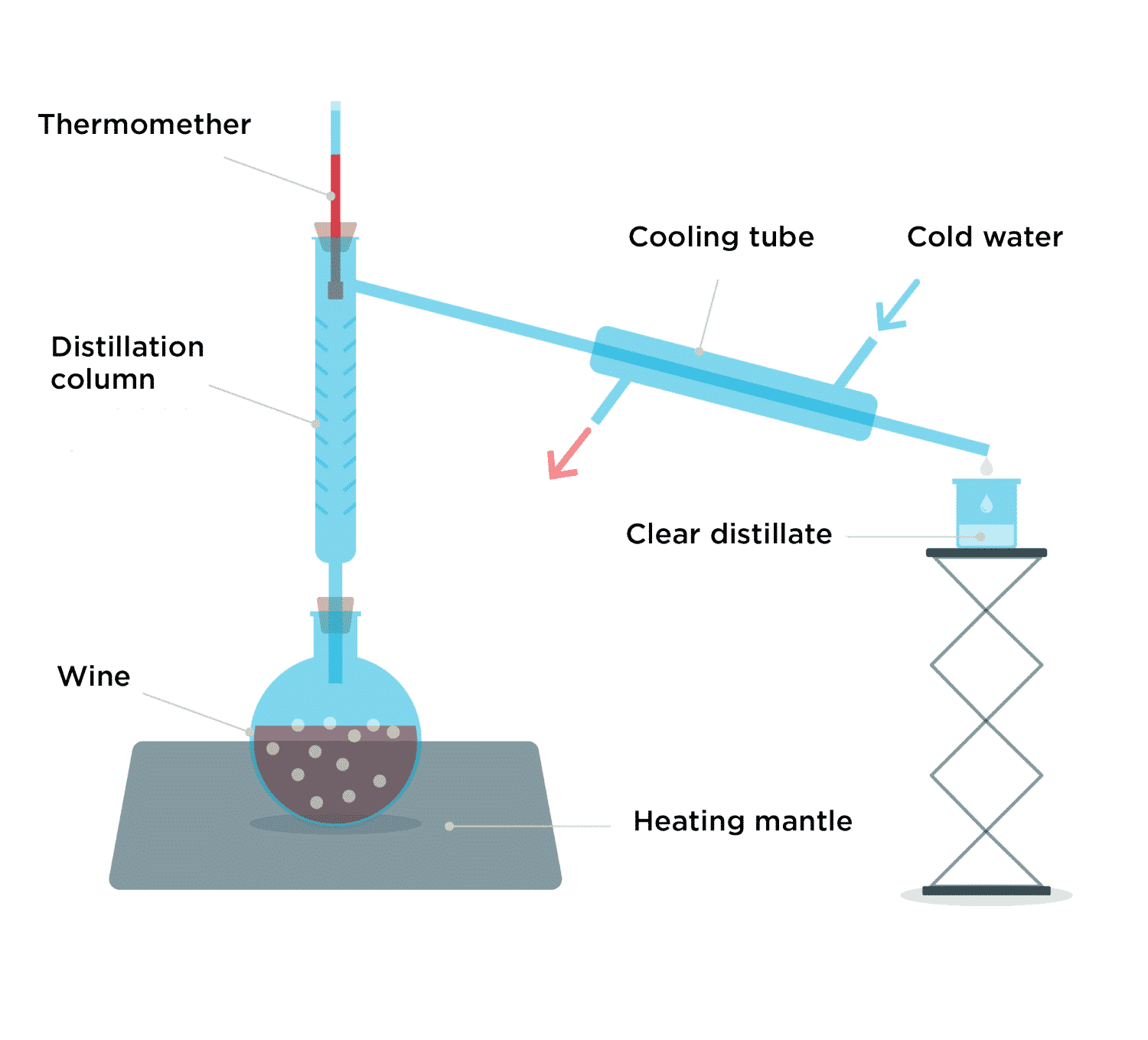
Indeed, when wine or fermented fruit purée is added to a flask and heated, vapors are released. When these vapors are condensed by cooling water, a clear distillate is produced that is 120-proof alcohol.
Thanks to the work of home distillers, supplemented mostly by the research of engineers in the oil sector, distillation now plays as important a role in industry as separation operations.
Let’s dig deeper into this technique, which is essentially founded on knowing the liquid-vapor equilibrium of the mixture to be separated. To make things concrete, let’s say we want to use distillation to separate a binary mixture of benzene (1) and toluene (2) available at pressure P = 1 atm. At the industrial scale, this separation occurs in a column with 19 trays.
The figure below is a diagram of the phases in the system we are studying, calculated at atmospheric pressure. This diagram is made up of the bubble curve (boundary between the liquid domain and the biphase domain) and the dew curve (boundary between the gas domain and the biphase domain). Between the two curves (inside the elliptical shape), the system is in liquid-vapor equilibrium. For any point M in the bi-phase domain, points L and V representing the liquid and vapor phases are located respectively on the bubble and dew curves. Thus, the x-axis shows the composition of each of the phases. At atmospheric pressure, the bubble temperature for benzene [Teb(1) = 353 K] is lower than that of toluene [Teb(2) = 384 K]. Therefore, it can be said that benzene is more volatile than toluene.
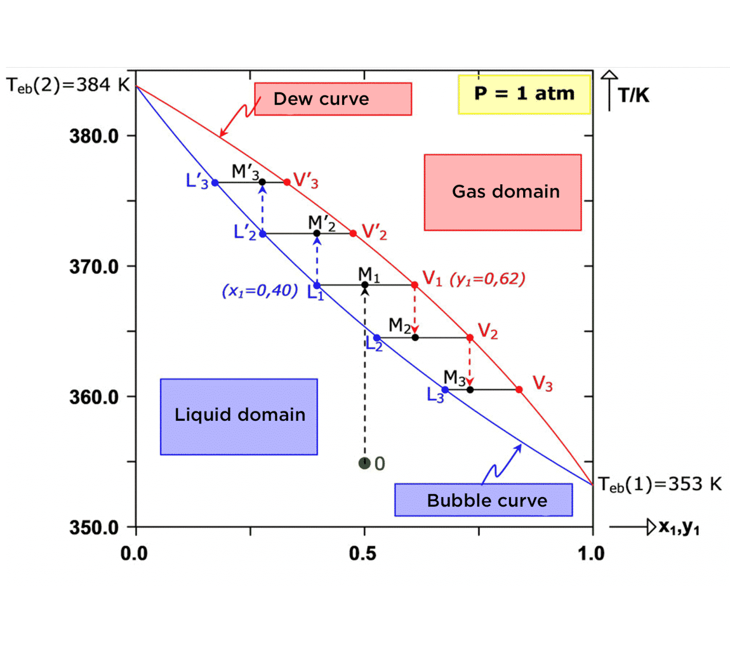
Let’s assume that the mixture to be separated, which is 50% benzene and 50% toluene, is stored in liquid form in a tank at temperature T0 = 355 K. The representative state point of the system is the green point (point 0) in the diagram.
By heating to temperature T1 = 367 K, a biphasic system is achieved, which is represented by point M1. The vapor phase (point V1) now has 62% benzene. Therefore, it has become concentrated in the more volatile component. Similarly, the liquid phase (point L1) contains 60% toluene, meaning that is has become concentrated in the heavier component. Thus, the two components have been partially separated because the initial equimolar mixture has yielded a liquid phase containing 60% toluene and a gas phase containing 62% benzene.
By repeating the procedure, it would be possible to obtain the two components with a purity near 100%.
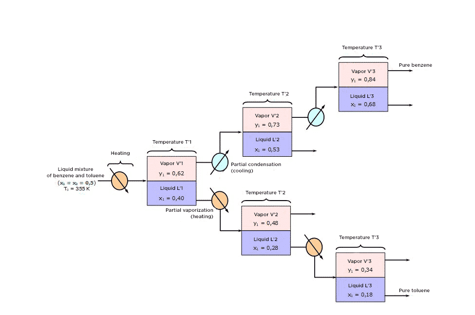
To do this:
1) Use cold to condense partially vapor V1 so as to obtain the liquid-vapor equilibrium L2-V2, then partially condense V2 to obtain the equilibrium L3-V3.
On générerait ainsi des phases vapeur (V1, V2, V3 …) de plus en plus riches en benzène c’est-à-dire en constituant volatil.
And, at the same time,
2) Use heat to partially vaporize liquid L1 so as to obtain the LVE L’2-V’2, then vaporize L’2 to obtain the equilibrium L’3-V’3. You would thus generate vapor phases (L1, L’2, L’3 …) that are increasingly rich in the heavy component (toluene).
At the industrial scale, such an arrangement would be hard to imagine because the quantities of benzene and toluene produced would be significantly lower than those initially introduced. The above diagram highlights the fact that the material streams L2, L3, V’2 and V’3are systematically eliminated from the separation process. To optimize the separation operation, you should recycle each liquid stream L2, L3,…,Li until elimination in the separation stage at level (i-1). Similarly, you will recycle each vapor stream V’2, V’3, … V’i toward the stage at level (i’-1). This results in a diagram of continuous industrial distillation principle:
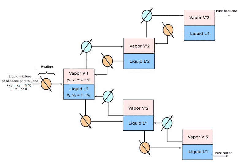
In practice, this succession of phase equilibrium is implemented in an isobaric distillation column with a continuous feed of the mixture to be separated. In addition, the column has two kinds of “materials” one at the top of the column where the condenser is (point of recovery of the distillate, i.e. the volatile component-enriched component) and one where the boiler is (point of recovery of the residue, i.e. the volatile component-depleted mixture). The countercurrent exchanges of material and heat exchanges are the result of the return to the column:
1) of a fraction of the liquid flow from the condenser. This downstreaming flow of cold material is the reflux in the column.
2) of a vapor stream from the boiler. This is a rising stream of hot product.
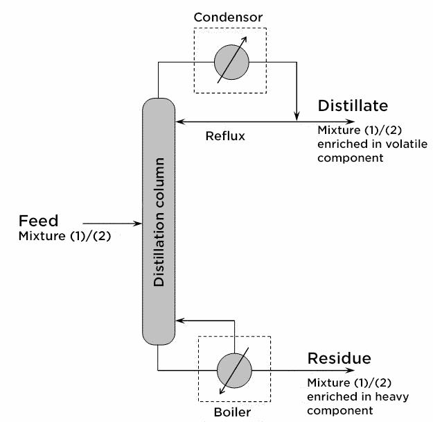
The part of the column located above the feed stage is called the enrichment section (or rectification section). The part of the column located below this stage is called the stripping section (or depletion section).
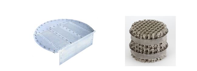
To ensure an optimum exchange between the descending liquid and the rising vapor, the column is equipped with trays or filled with structured packing.
However, like many material transfer operations, the sizing of a distillation column is based on the notion of a theoretical plate: this is the stage at which the liquid and vapor phases would be in thermodynamic equilibrium. Because contact times are limited, the actual plates of a distillation column always prevent thermodynamic equilibrium from being reached. Therefore, in practice, there must be more actual trays than the number of theoretical trays estimated from the isobaric phase diagram. To account for the fact that fluids leaving one stage are not at equilibrium, the overall efficiency EG of the column is defined as:
EG = number of theoretical trays/number of actual trays
This figure is easy to measure experimentally in a given installation.